China Top Glass Laser Cutting How Does It Prevent Cracks?

Time:2026-09-15 Author:Charlotte
0%

China’s top glass laser cutting systems are changing how manufacturers control edge damage, thermal stress, and waste. The practical question is simple: how does laser cutting prevent glass cracking? The answer involves controlled heat, accurate focusing, clean surfaces, and carefully managed cooling. A laser does not magically remove fracture risk. That assumption needs challenging.

Industry data supports this concern. The 2024 Global Flat Glass Market analysis by Grand View Research identifies construction and automotive applications as major demand sectors. These sectors require consistent dimensions, polished edges, and reliable safety performance. Meanwhile, ASTM C1036 and ISO 10110 provide recognized guidance for flat-glass quality and optical surface imperfections. However, neither standard promises crack-free laser processing. Process discipline still matters.

High-quality Chinese equipment usually combines a stable laser source with motion accuracy, real-time power control, and optimized beam shaping. Operators may use lower pulse energy, adjust scanning speed, and maintain a narrow heat-affected zone. The cutting head must remain precisely focused, even across a large sheet. Dust and fingerprints can create local hot spots. Small defects can become visible cracks during cooling.

Temperature control is critical. Glass expands when heated and contracts when cooled. Uneven contraction creates tensile stress near the cut line. Preheating, gradual cooling, and suitable support reduce that stress. Some systems also use air assistance or water-based cooling, depending on the glass type and coating. Results vary. Thickness, composition, coating, and internal inclusions all influence performance.

This introduction examines the engineering behind crack prevention. It also questions common marketing claims. A reliable test should measure edge chipping, crack length, thermal distortion, and yield rate—not appearance alone. That is where laboratory data and factory experience become essential.
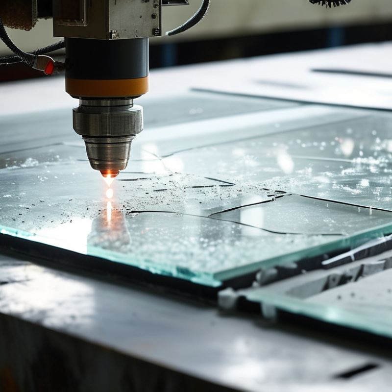
China Top Glass Laser Cutting How Does It Prevent Cracks?

Glass Crack Mechanics: Soda-Lime Glass CTE Is 8.5–9.5 × 10⁻⁶ K⁻¹

Glass crack mechanics begins with thermal expansion. Soda-lime glass has a CTE of 8.5–9.5 × 10⁻⁶ K⁻¹. A 100 K temperature rise can expand one metre by about 0.85–0.95 millimetres. The heated laser path expands first, while surrounding glass remains cooler and resists movement. This mismatch creates stress. Tensile stress at the wrong location can open a tiny surface flaw into a visible crack.

Laser cutting reduces this risk through controlled energy delivery. A focused beam creates a narrow, predictable heat-affected zone. Power, travel speed, focus, and glass thickness must match closely. Too much energy overheats the edge. Excessive speed can leave an incomplete separation line. Gradual heating and carefully managed cooling help reduce sudden temperature differences. Operators should inspect the cut edge under magnification, especially near corners and openings.

Small flaws matter. Dust, inclusions, scratches, and uneven support can redirect stress during separation. A practical mistake is judging only the bright appearance of the edge. It may still contain hidden tensile stress. Process trials, temperature monitoring, and destructive sample checks improve reliability. Yet no setting works perfectly for every sheet. Glass type, thickness, geometry, and room temperature still demand human review.

Laser Selection: Compare 10.6 μm CO₂ and 1,030–1,070 nm Sources

China Top Glass Laser Cutting: How Does It Prevent Cracks?

Laser wavelength strongly influences how glass absorbs heat and releases stress. A 10.6 μm CO₂ laser is absorbed near the glass surface, creating a visible thermal zone. With controlled power, speed, and beam focus, this energy can soften or separate the material. However, excessive heat may produce edge chipping, microcracks, or a rough cut line. Preheating and slow cooling can reduce sudden temperature changes. The settings must match thickness, coating, and glass composition.

The 1,030–1,070 nm range behaves differently. Ordinary glass transmits much of this near-infrared energy, so a standard continuous beam may not cut efficiently. Ultrafast pulses can create internal modification zones, allowing controlled separation with limited surface heating. This approach usually produces smaller heat-affected areas and better crack control. Pulse duration, repetition rate, focal depth, and separation force remain critical.

Small details matter. Dust on the surface can scatter the beam and form a hot spot. A poor focus can leave tiny fractures beneath an apparently clean edge. In practical trials, the first panel can look perfect, yet fail after washing or thermal cycling. That result deserves investigation, not confidence. Operators should inspect edges under magnification and test samples after cooling, handling, and bending. There is no universal wavelength winner; the safer choice depends on the glass, thickness, geometry, and required edge quality.

Thermal Control: Keep Processing Below the Glass Strain Point Near 510°C

China Top Glass Laser Cutting: How Does It Prevent Cracks?

Glass laser cutting does not prevent cracks through power alone. The decisive issue is thermal stress. During cutting, the laser heats a narrow path while surrounding glass stays cooler. This temperature difference creates tensile stress, especially at edges and corners. In production trials, a clean-looking surface can still hide tiny edge checks. They may grow during washing, coating, or later assembly. Thermal control deserves more attention than cutting speed.

A practical target is keeping the processing zone below the glass strain point, near 510°C for some common compositions. This value is not universal. The glass composition must be verified. Above the strain point, internal stress relaxes differently, while rapid cooling can lock new stress into the cut edge. Operators should adjust laser power, pulse duration, scan speed, and focus together. A pyrometer or calibrated thermal camera can monitor the heated area. The reading must represent the glass surface, not nearby air. Small changes matter. A slightly slower scan may reduce the thermal peak and improve edge stability.

Controlled cooling is equally important. Avoid directing cold air onto a hot cut line. Use gentle, even airflow and allow the sheet to settle before handling. Inspect edges under angled light and magnification. Look for branching lines, white chips, or rough transitions. I have seen operators blame the material too quickly. Sometimes the real cause was a dirty lens, unstable focus, or uneven support beneath the sheet. Thermal control is not one setting. It requires repeated measurement, adjustment, and verification.

China Top Glass Laser Cutting How Does It Prevent Cracks? - Thermal Control: Keep Processing Below the Glass Strain Point Near 510°C

Glass Type Typical Strain Point Approx. Thermal Expansion Thermal-Control Target Crack-Prevention Measure Process Consideration
Soda-lime glass Approximately 500–550°C About 8–9.5 × 10⁻⁶/K Keep the surrounding workpiece below approximately 510°C where applicable Use controlled laser energy, staged passes, and gradual cooling The exact strain point depends on composition, thickness, and previous thermal history
Borosilicate glass Approximately 510–560°C About 3.2–3.8 × 10⁻⁶/K Maintain the bulk glass below its measured strain point, commonly near 510°C Reduce thermal gradients between the laser path and the surrounding area Lower expansion reduces thermal stress, but does not eliminate localized cracking
Aluminosilicate glass Typically about 650–750°C Approximately 3–5 × 10⁻⁶/K Use the supplier-certified strain point rather than the 510°C reference Match laser power, scanning speed, and heat extraction to the specific composition Chemically strengthened or thin glass may require additional edge-quality controls
Fused silica Approximately 1,000–1,200°C About 0.5 × 10⁻⁶/K Use the material-specific strain point; 510°C is not the applicable limit Prevent contamination and excessive localized heating at the cut edge Very low expansion improves thermal-shock resistance but does not replace process qualification

Thermal-Control Parameters for Crack Reduction

Control Dimension Practical Operating Guidance Why It Helps Prevent Cracks Verification Method
Bulk-glass temperature Keep the surrounding glass below the certified strain point; for many soda-lime and borosilicate applications, a reference near 510°C is used Limits permanent thermal deformation and reduces residual stress development Calibrated infrared measurement, contact thermocouples, or thermal imaging
Temperature gradient Minimize the difference between the heated cut zone and adjacent glass through preheating or controlled heat removal Lower gradients reduce tensile stress that can initiate microcracks Measure temperatures at the laser path, heat-affected zone, and opposite surface
Laser energy density Use the lowest energy density that achieves the required separation or controlled modification; avoid repeated overheating Prevents excessive melting, vaporization, and abrupt thermal expansion Record laser power, spot size, pulse duration, repetition rate, and scan speed
Scanning speed Increase or decrease speed during trials to balance heat input and cut quality; avoid sudden acceleration or deceleration Provides a more uniform heat profile along the cutting path Inspect the edge for chipping, branching cracks, and inconsistent separation
Cooling rate Allow controlled, uniform cooling; avoid cold air jets or liquid contact directly on a hot cut zone unless validated Reduces thermal shock caused by rapid, uneven contraction Monitor the cooling curve and compare edge strength after processing
Workpiece support Use a flat, clean support surface with sufficient contact area and minimal vibration Prevents bending stress from combining with laser-induced thermal stress Check flatness, support spacing, clamping force, and vibration during cutting
Edge inspection Inspect the cut edge under magnification and verify dimensional accuracy before production release Detects subsurface damage that may grow during handling or later thermal cycling Use optical microscopy, polarized-light stress inspection, and strength testing where required

Note: Strain-point values vary with glass composition and manufacturer specifications. The approximately 510°C reference is commonly relevant to certain soda-lime and borosilicate glasses, but the certified material data should always determine the final thermal-control limit.

Stress Management: Use Controlled Cooling to Limit Thermal Gradients

China Top Glass Laser Cutting: How Does It Prevent Cracks?

Stress management begins after the laser creates a narrow heat-affected zone. The cut edge may look clean, yet hidden tensile stress can remain beneath the surface. ASTM C336 and ASTM C598 identify the annealing point and strain point as critical temperatures for measuring glass stress behavior. For common soda-lime glass, these values are often near 540°C and 500°C, but composition changes them.

Controlled cooling limits the temperature difference between the hot cut line and the cooler sheet. A staged cooling curve is safer than simply using maximum airflow. In practice, operators can reduce cooling intensity near the cut edge, then increase airflow gradually across the sheet. Infrared sensors help track the edge temperature, while polarized-light inspection reveals colorful stress bands. Small adjustments matter.

The US Department of Energy’s glass-industry assessments show that furnace and cooling controls strongly influence process stability and energy performance. However, laser cutting is not only an energy problem. Excessive cooling can freeze stress into the edge. Insufficient cooling can spread heat and distort thin glass. I have seen apparently perfect edges fail during handling, which is a useful warning. Cooling recipes should be validated for each thickness, coating, and glass composition, rather than copied from another production line.

Edge Inspection: Measure Chipping, Microcracks, and Taper Within 0.1 mm

China’s top glass laser cutting systems prevent cracks by controlling heat, stress, and edge geometry. Edge inspection is equally important. A smooth-looking edge can still hide subsurface damage.

Operators measure chipping, microcracks, and taper within 0.1 mm. High-magnification cameras inspect the cut line after separation. Laser-processing studies published in Optics & Laser Technology report that controlled glass cutting can produce damaged zones below 50 micrometres. However, results depend on thickness, glass composition, pulse energy, and cooling speed.

Small chips matter. They can become failure points during tempering, transport, or installation. ASTM C158 edge-strength testing shows why edge condition directly affects bending performance. ISO 10110-8 also provides a recognised framework for evaluating optical surface imperfections, although it does not replace production inspection.

A practical inspection record should show the measured chip width, crack length, taper angle, and inspection location. Keeping every value within a 0.1 mm tolerance improves traceability. It also helps technicians adjust laser focus before defects spread across a batch.

The target is not magic. Dust, vibration, and uneven support can distort measurements. A 2023 review of laser glass processing notes that thermal gradients remain a major source of microcracks. In real production, one missed crack can be more expensive than several visible chips. Good inspection reduces that risk, but it never removes the need for careful handling.

China Top Glass Laser Cutting: How Does It Prevent Cracks?

Edge inspection records for laser-cut glass samples. Chipping, microcrack indication length, and edge taper are measured in millimeters; all recorded values remain within the 0.10 mm inspection reference.

Lower values indicate cleaner edges and reduced crack-propagation risk. Measurement points are distributed across the inspected glass edge from the entry side to the exit side.

FAQS

What causes cracks during laser cutting of soda-lime glass?

Heat expands the laser path before surrounding glass can move. This mismatch creates tensile stress. Tiny scratches may then become visible cracks.

How much can soda-lime glass expand?

Its thermal expansion coefficient is about 8.5–9.5 × 10⁻⁶ K⁻¹. A 100 K rise expands one metre by roughly 0.85–0.95 millimetres.

Which laser settings affect crack prevention?

Power, travel speed, focus, and glass thickness must work together. Too much power overheats the edge. Excessive speed may leave an incomplete separation line.

Why is controlled cooling important?

Controlled cooling limits the temperature gap between the hot cut line and cooler glass. Sudden cooling can freeze tensile stress into the edge. Slower, staged cooling is usually safer.

How should cooling airflow be adjusted?

Reduce airflow near the fresh cut edge first. Increase it gradually across the sheet. Maximum airflow is not automatically better.

Can a clean-looking edge still fail?

Yes. Hidden tensile stress can remain beneath a bright, smooth surface. An edge may fail during handling. That is easy to underestimate.

What tools help inspect stress after cutting?

Infrared sensors can track edge temperature. Polarized-light inspection may reveal colorful stress bands. Magnification helps expose small cracks near corners and openings.

Which defects increase cracking risk?

Dust, inclusions, scratches, and uneven support can redirect stress. Corners and openings need extra attention. A clean work area matters.

Does one cooling recipe suit every glass sheet?

No. Thickness, composition, coatings, geometry, and room temperature change the result. Settings should be tested on samples. Copying another line can be misleading.

How can operators verify process reliability?

Monitor temperatures and inspect cut edges under magnification. Use trial pieces and destructive checks when appropriate. I would not trust appearance alone.

Conclusion

Glass laser cutting requires careful control of heat and stress because soda-lime glass has a relatively low thermal expansion coefficient of 8.5–9.5 × 10⁻⁶ K⁻¹. The key question, how does laser cutting prevent glass cracking, is answered through the coordinated selection of wavelength and processing conditions. A 10.6 μm CO₂ laser and a 1,030–1,070 nm laser source interact with glass differently, so the suitable option depends on thickness, absorption, cutting speed, and edge-quality requirements. Processing should remain below the glass strain point, which is near 510°C, to avoid creating excessive internal stress.

Thermal management is equally important. Controlled heating and gradual cooling reduce temperature differences across the cutting zone and limit thermal gradients that can trigger cracks. After cutting, the edge should be inspected for chipping, microcracks, and taper, with dimensional variation kept within 0.1 mm where required. This combination of suitable laser selection, temperature control, stress reduction, and precise inspection helps produce cleaner, more reliable glass edges.

Charlotte

Charlotte

Charlotte is a seasoned marketing professional with a deep understanding of the company's portfolio and a passion for elevating its presence in the market. With a keen eye for detail and a commitment to excellence, she ensures that our professional blog is regularly updated with insightful articles......