Top Ways Automation Improves PCB Production Lines

Time:2026-10-31 Author:Mason
0%

PCB production lines depend on precision, timing, and consistent material handling. A single board may pass through solder-paste printing, component placement, reflow, and inspection. Each stage creates opportunities for small errors, from misaligned components to uneven solder deposits. Small delays matter. When operators must move materials or inspect every board manually, output can vary between shifts. Automation connects these steps with programmable equipment, sensors, and production software. It can help machines place components accurately and keep work moving at a steady pace. Automated optical inspection can flag defects, such as a shifted resistor, before boards reach later stages. These tools support quality control, but they do not guarantee perfect products.

The practical question is: how does automation improve pcb production lines? It improves repeatability, traceability, and the use of production data. For example, a line can record placement errors and equipment stoppages, helping technicians investigate recurring problems. Robots may also handle repetitive tasks, while operators focus on setup, maintenance, and exception handling. The gains depend on sensible integration. A poorly tuned feeder can simply move a bottleneck downstream, and automated inspection still needs reliable settings and human review. This article explores the main ways automation affects PCB production, from faster assembly to more consistent quality. It also considers where careful planning matters, because adding machines alone does not make a line efficient. The best results come from matching automation to the board design, production volume, and skills of the people running the line.
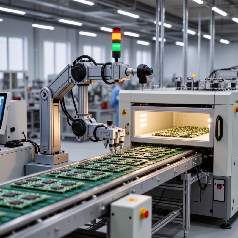
Top Ways Automation Improves PCB Production Lines

Automated Material Handling and PCB Preparation

Automated material handling begins before a PCB reaches the assembly line. Conveyors and lift systems can move panels between storage, inspection, and preparation with fewer manual transfers. Barcode scans link each panel to its production order, helping operators catch mix-ups early. Small errors matter. A reversed stack or damaged panel edge can interrupt a carefully balanced line.

Preparation equipment can clean board surfaces, control drying conditions, and align panels for printing or component placement. Sensors check position and detect some visible defects, while controlled handoffs reduce bumps and handling marks. These steps are useful when boards vary in size or move through several stations. Yet sensors do not notice everything. A dusty lens or poorly set threshold may let a defect pass, so routine checks still matter.

Good automation also records panel identity, process time, and inspection results. That information helps teams trace recurring issues to a storage area or handling station, rather than guessing. Operators should confirm that recipes match board thickness and panel layout before a run. Even a smooth conveyor can carry the wrong stack efficiently. Practical systems need clear alarms, accessible maintenance points, and room for human judgment when readings look unusual.

Precision Component Placement and Soldering

Automated component placement depends on more than speed. A vision system reads board fiducials and corrects small shifts before components reach the solder paste. Feeders must present parts consistently, while vacuum nozzles need the right size and pickup force. A misplaced resistor can interrupt a whole assembly. Small details matter.

Placement accuracy also depends on board support and machine calibration. A setup can pass initial checks, yet drift after a feeder reel change. That is easy to miss. Operators should verify pickup rates, inspect placement offsets, and compare results across boards. Repeated defects may point to a worn nozzle, unstable paste, or incorrect component data—not just a machine fault.

Soldering automation adds another layer of control. Reflow ovens use defined temperature zones and conveyor speeds to heat joints steadily, while wave or selective soldering systems target specific connections. Thermocouples on sample boards help confirm the real thermal profile. Too little heat can leave weak joints; too much can damage sensitive parts. Automated optical inspection can flag bridges, shifted components, or insufficient solder, but it cannot explain every root cause. People still need to review the evidence and adjust the process carefully.

Top Ways Automation Improves PCB Production Lines - Precision Component Placement and Soldering

Representative process data and operating ranges are provided for planning purposes. Actual results depend on equipment, board design, component mix, solder materials, and process settings.

Production Area Automation Method Representative Data or Control Production Benefit
Component placement accuracy Vision-guided pick-and-place systems align components using fiducials and component recognition. Typical machine placement accuracy is approximately ±25–50 µm; specifications vary by machine, component, and operating conditions. More consistent placement of fine-pitch and small components, with fewer misalignment-related defects.
Placement throughput Automated feeders and placement heads deliver components continuously according to programmed board data. Rated placement speeds for modern SMT equipment commonly range from tens of thousands to over 100,000 components per hour. Actual line output is lower when changeovers, board handling, and product mix are included. Higher repeatable output and less dependence on manual component handling.
Solder paste deposition Automated stencil printers control print alignment, pressure, speed, and separation; solder paste inspection measures deposited paste. Inspection systems can measure paste area, height, volume, and offset. Acceptance limits are set for the specific board and component geometry. Earlier detection of insufficient, excessive, or misaligned paste before components are placed.
Reflow soldering Conveyorized reflow ovens use programmed heating and cooling zones, with thermocouples used to verify the board profile. For common lead-free SAC alloys, the liquidus temperature is about 217°C. A typical peak-temperature range is approximately 235–250°C, subject to the solder-paste and component specifications. More consistent heating across boards and reduced variation in solder-joint formation.
Inline solder-joint inspection Automated optical inspection checks visible component position, polarity, and solder-joint features after assembly. AOI can inspect boards inline; X-ray inspection is generally used when hidden joints, such as those under many BGA packages, need examination. Faster identification of visible assembly defects and improved feedback to placement and soldering processes.
Process traceability Manufacturing systems link board identifiers with placement, inspection, and reflow-process records. Records can include product and lot identifiers, inspection results, and reflow-profile data when connected systems capture them. Supports defect investigation, process comparison, and controlled corrective action.

In-Line Inspection and Defect Detection

Inline inspection gives PCB lines a chance to catch defects before they become expensive rework. Overhead cameras can check solder joints, component placement, polarity marks, and missing parts within seconds. A board with a shifted resistor may look fine from a distance. Under angled lighting, its edge can reveal the error. Automated optical inspection (AOI) compares these images with programmed rules and flags suspicious areas for review.

The 2019 Smart Factory Study reported that 86% of surveyed manufacturers expected smart-factory solutions to drive competitiveness within five years. That figure is not an AOI performance measure, but it reflects growing investment in connected production. Linking inspection results to machine settings can help teams spot recurring patterns, such as defects clustering after a stencil change. False calls happen. Poor lighting, reflective solder, or outdated inspection rules can send good boards for unnecessary review. Teams should validate thresholds against real defect samples and track false-reject rates alongside escape rates. One awkward truth: inspection data is only useful when operators have time to act on it. A camera can detect a skewed connector; it cannot explain why the feeder keeps shifting. Regular calibration and clear feedback between inspection and process teams keep detection useful, not merely fast.

Top Ways Automation Improves PCB Production Lines: In-Line Inspection and Defect Detection

Illustrative example: defect detection rate by inspection stage. Values are for demonstration and are not universal industry benchmarks.

Automated in-line inspection can check every board consistently and flag potential defects earlier, helping teams focus review and rework where they are most needed.

Real-Time Process Control and Production Optimization

Real-time process control helps PCB production lines respond before small variations become costly defects. Sensors can track solder-paste thickness, placement accuracy, oven temperatures, and conveyor speed. When a reading drifts, the system can flag the station or adjust a permitted setting. Operators still need to confirm unusual alerts; automation can misread a dirty sensor. Fast feedback matters. A temperature shift of only a few degrees may affect solder joints across many boards. Reviewing live data alongside inspection results helps teams distinguish a temporary fluctuation from a recurring process issue.

Tips: Set practical alert limits using verified process data, not guesswork. Check sensor calibration on a regular schedule, and record manual adjustments. A simple trend chart can reveal gradual drift that a single measurement misses. Keep the response clear: who checks the alert, and what happens next?

Production optimization comes from connecting control data with the pace of the line. If a placement machine slows, downstream stations may sit idle, while an overloaded inspection step can create a queue. A shared dashboard can show cycle times, stoppages, and first-pass yield in one view. Teams can then balance workloads, schedule maintenance around actual equipment behavior, and compare shifts fairly. Still, higher output is not always better. Rushing a change without a trial can increase rework, and some data patterns need human judgment. Process control improves steadily, but it is not magic.

Traceability, Maintenance, and Continuous Improvement

Automated PCB lines can connect each board’s ID with panel position, solder-paste inspection, placement data, reflow settings, and final optical inspection. If a solder bridge appears, engineers can compare the affected boards with nearby production runs instead of relying on memory. This does not prove one cause. But timestamps and machine settings can narrow the search and help teams isolate a process window. Records need consistent naming and calibrated sensors; otherwise, precise-looking data can mislead.

Maintenance systems can track feeder errors, nozzle changes, temperature drift, and repeated stoppages. A rising placement-error count may prompt a nozzle check before defects spread across a full shift. Small signals matter. Yet automated alerts can create noise when thresholds are poorly set. Operators should review recurring warnings against actual machine condition, then adjust the maintenance schedule with documented evidence. A checklist alone will not fix a worn component.

Continuous improvement works best when teams review a small set of useful measures, such as first-pass yield, defect location, and unplanned downtime. They can test one change at a time, record the result, and keep it only when the data supports it. Not always. Production conditions vary, and a successful adjustment on one product may fail on another. That limitation deserves a place in the process record.

FAQS

How does automated material handling help prepare PCBs?

Conveyors and lift systems move panels between storage, inspection, and preparation. Barcode scans help catch order mix-ups early. Less hand-carrying.

What can preparation equipment check?

It can clean and dry board surfaces, align panels, and detect some visible defects. A dusty sensor lens may still miss one.

Why must operators check production recipes?

Recipes should match board thickness and panel layout before a run. A conveyor can move the wrong stack perfectly. That is worth remembering.

What affects automated component placement accuracy?

Vision systems correct small board shifts, while feeders and vacuum nozzles must present parts consistently. A worn nozzle can matter more than expected.

How do teams verify soldering temperatures?

Thermocouples on sample boards help confirm the actual reflow profile. Too little heat weakens joints; too much may damage sensitive parts.

What can optical inspection detect after assembly?

It can flag solder bridges, shifted components, or insufficient solder. It cannot explain every cause. People still need to review the evidence.

How does traceability help investigate defects?

Teams can connect board IDs with placement data, process settings, and inspection results. Timestamps narrow the search, but they do not prove one cause.

How should teams use maintenance alerts and production data?

They can review repeated feeder errors, nozzle changes, and downtime alongside first-pass yield. Test one process change at a time. Results may not transfer to another product.

Conclusion

Automation improves PCB production by making each stage faster, more consistent, and easier to manage. Automated material handling and board preparation reduce manual movement, support a steady flow of work, and help ensure that each PCB is ready for assembly. Precision placement equipment positions components accurately, while controlled soldering processes create reliable connections and reduce variation between boards.

In-line inspection can identify placement or soldering defects early, allowing issues to be addressed before they affect later stages. Real-time process data helps teams adjust production settings, balance workloads, and reduce avoidable downtime. Traceability records connect each board with relevant production information, while maintenance planning helps keep equipment operating reliably. Together, these capabilities explain how does automation improve pcb production lines: it supports dependable quality, efficient output, and continuous improvement throughout manufacturing.

Mason

Mason

Mason is a seasoned marketing professional with a deep expertise in the company's offerings and a passion for driving brand awareness. With a strong background in digital marketing strategies, he has an innate ability to connect with diverse audiences and effectively communicate product benefits.......