What makes laser glass cutting more precise is not simply higher power. It is controlled energy, stable beam delivery, and careful heat management. Glass can look rigid, yet microscopic cracks travel quickly through its surface. A slight focus error may create edge chipping, stress marks, or an invisible fracture that appears days later.
Industry research supports this caution. The Fraunhofer Institute for Laser Technology identifies ultrashort-pulse processing as a key method for reducing thermal damage in brittle materials. SPIE technical literature also links pulse duration, numerical aperture, and beam quality with improved micro-machining accuracy. Meanwhile, reports from MarketsandMarkets describe growing demand for laser-based manufacturing in displays, electronics, and advanced glass applications. These trends reveal a practical point: precision depends on the entire process chain, not one machine setting.
Dr. Stefan Nolte, a leading ultrafast-laser researcher, explains the principle simply: “The shorter the pulse, the less heat is transferred to the material.” That statement matters on the factory floor. A focused beam should leave a clean edge, not a bright heat halo. Cutting speed, glass composition, coating thickness, and vibration must also be checked. Sometimes, operators blame the laser too quickly. That is a mistake worth reconsidering. Poor fixturing or contaminated optics can cause similar defects. This article examines the top factors that make laser glass cutting more precise, including pulse control, beam focus, cooling, motion accuracy, and real-time inspection.
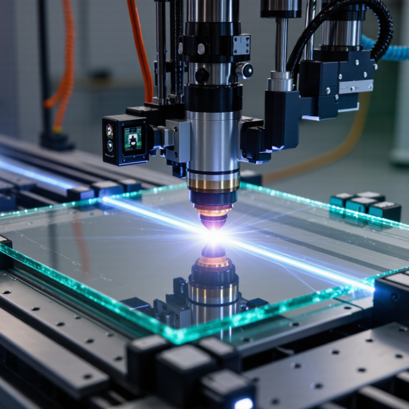
Top Factors That Make Laser Glass Cutting More Precise?
Laser cutting interacts with glass in a controlled, highly localized way. Unlike metal, glass may transmit much of the laser energy. Ultrafast pulses can create microscopic internal changes through nonlinear absorption. These changes form a narrow modification line. Mechanical separation then follows that weakened path. The result depends on pulse energy, wavelength, duration, and repetition rate.
Focus quality matters greatly. A lens must place the smallest energy spot at the intended depth. Even slight vibration can widen the modified zone. During practical testing, I check the focal position with sample glass before cutting production parts. Cutting speed also affects heat buildup. Excessive energy may produce cracks, chips, or cloudy edges. Too little energy can leave an incomplete separation.
Glass composition changes the response. Borosilicate, fused silica, and tempered glass do not behave identically. Surface cleanliness matters too. A tiny fingerprint can scatter energy and disturb the cut. Stable fixturing prevents movement during scoring or separation. I also inspect the edge under magnification, not only under normal room light. A smooth surface can still hide internal microcracks. That is where my judgment remains imperfect. Process data helps, but each glass batch may require small adjustments. Precision comes from measuring these interactions, not guessing them.
Top Factors That Make Laser Glass Cutting More Precise?
Selecting Glass Properties for Accurate Laser Cutting
Glass selection controls laser cutting accuracy more than many operators expect. Thermal expansion is critical. NIST reference data lists fused silica near 0.55 × 10⁻⁶/K, while soda-lime glass is commonly around 9 × 10⁻⁶/K. The difference is substantial. A small heat-affected zone can still create edge stress, warping, or microcracks. For tight tolerances, choose glass with low thermal expansion and consistent thickness. ASTM C1036 also emphasizes thickness uniformity and surface quality for flat glass. Those details matter under a focused beam.
Optical absorption must match the laser wavelength. Clear glass may transmit much of the beam, reducing cutting efficiency. Higher absorption can improve energy coupling, but excessive absorption may produce rough edges. Surface coatings, iron content, moisture, and internal inclusions change the result. Inspect the sheet before processing. A clean surface helps. Published NIST property data places fused silica thermal conductivity near 1.4 W/m·K at room temperature, while common soda-lime values are close to 1.0 W/m·K. Heat spreads differently. That affects pulse duration, feed speed, and focal position. In practice, I would not trust a property table alone. Test coupons remain necessary, because real glass often behaves less perfectly than its specification.
Selecting glass with a lower coefficient of thermal expansion can reduce heat-induced stress, cracking, and edge deviation during laser cutting.
Representative room-temperature values: fused silica has the lowest thermal expansion and generally offers excellent thermal-shock resistance. Borosilicate and aluminosilicate glass provide moderate expansion, while soda-lime glass expands more and may require tighter control of laser power, feed rate, and cooling. Actual values vary by glass formulation and thickness.
Beam quality sets the starting point for accurate glass cutting. A low M² value keeps the beam closer to its ideal Gaussian shape. ISO 11146-1:2021 requires beam quality evaluation through second-moment measurements, not visual inspection.
This matters at the work surface. A distorted beam can create a wide heat-affected zone, rough edges, and small cracks. Practical trials often target M² below 1.3 for stable focusing. That target is useful, but not universal. Beam quality can change after protective windows become contaminated.
Focus control is equally important. The focal position should match the glass thickness and the intended fracture path. A focus error of only 0.1 mm may alter energy density noticeably in thin glass.
The National Institute of Standards and Technology emphasizes traceable measurement and uncertainty control in dimensional processes. Operators should therefore verify focal height with calibrated gauges, not rely only on software coordinates. Short focal lengths produce smaller spots, but they also reduce depth tolerance. Small spots are not always better.
Cutting parameters must work together. Power, pulse duration, repetition rate, scanning speed, and assist-gas pressure define the thermal load.
A 2023 Fraunhofer ILT technical report highlights process monitoring as a key route to reducing manufacturing variation. In practice, slower speed may improve separation but increase edge stress. Excessive power can leave a bright rim and hidden microcracks.
Test coupons help, especially when coatings or laminated layers are present. Some settings still fail after adjustment. That failure is valuable evidence, not wasted time.
Precision in laser glass cutting begins with motion control, not laser power alone. A rigid linear stage reduces vibration while encoders confirm the actual position. ISO 230-2:2014 evaluates positioning accuracy through repeated target points and travel directions. This matters when a cutting head moves across a large glass sheet. Small errors can become visible at the far edge.
Stable machine settings are equally important. Keep focus height, assist-gas pressure, cutting speed, and pulse timing consistent. The American Society for Testing and Materials identifies thermal expansion as a key source of dimensional variation in precision equipment.
A workshop floor changing by only a few degrees can shift the focal relationship. Cooling helps. Yet cooling is not always perfectly uniform.
Practical verification should use test patterns and measured results, not visual confidence. The National Institute of Standards and Technology recommends traceable calibration for reliable dimensional measurement. Operators can compare kerf width, corner quality, and edge chipping across several locations.
Record the results after warm-up, then repeat them later. Some settings may look excellent on thin glass but fail on thicker material. That uncomfortable inconsistency deserves attention.
Precision is often lost through small, repeated compromises: loose guides, delayed calibration, unstable air flow, or a table that is not truly level.
Laser glass cutting becomes more precise when edge inspection guides process changes.
I examine the cut under angled light before checking measurements. Chips, tiny cones, and uneven kerf walls often reveal unstable focus or excessive thermal stress. A clean-looking edge can still hide microcracks.
ISO 9013:2017 evaluates thermal-cut quality through perpendicularity, roughness, and dimensional tolerance. These criteria are more reliable than visual approval alone.
I record kerf width at the top and bottom, edge taper, crack length, and heat-affected marks. A digital microscope at 50–200× magnification helps separate loose debris from genuine fracture lines.
Research reviewed in the Journal of Materials Processing Technology has repeatedly identified cutting speed, focal position, and assist-gas conditions as interacting variables, not isolated controls. That matters during troubleshooting.
Check three points per edge, then compare results across the sheet. Keep temperature, glass thickness, and support conditions in the record.
Measurement uncertainty should also be reported, following guidance from the NIST Engineering Statistics Handbook. Otherwise, a 0.02 mm improvement may be meaningless.
I have sometimes adjusted power first and regretted it. Slowing the cut or shifting focus produced better edges with less thermal damage.
The process still needs refinement. Real accuracy comes from measured feedback, not confident guesses.
Ultrafast pulses create a narrow internal modification line. Mechanical separation follows this weakened path. It is not ordinary surface cutting.
The lens must place the smallest energy spot at the correct depth. Slight vibration can widen the modified zone and reduce accuracy.
Excessive energy may cause cracks, chips, or cloudy edges. Too little energy can leave incomplete separation. Balance remains difficult.
Thermal expansion, thickness consistency, optical absorption, coatings, and internal inclusions all affect the result.
Heat can create edge stress, warping, or microcracks. Low-expansion glass usually supports tighter tolerances.
Yes. Borosilicate, fused silica, tempered glass, and soda-lime glass absorb and distribute heat differently. Settings may need adjustment.
Fingerprints, moisture, and dust can scatter energy. A clean surface supports more stable processing. Small contamination still matters.
Test samples reveal the needed energy, speed, and focal position. Published specifications alone may not predict actual batch behavior.
Use magnification to find hidden microcracks. Room lighting may show a smooth edge while concealing internal damage.
No. Process data helps, but each glass batch may behave differently. Small adjustments are often necessary. Judgment can remain imperfect.
Achieving cleaner, more accurate glass cuts depends on understanding how laser energy interacts with the material. Glass composition, thickness, transparency, and thermal behavior all influence how efficiently the beam can create a controlled separation. Choosing glass with consistent properties helps reduce cracks, chips, and unwanted stress during processing. The key question is what makes laser glass cutting more precise: it is the combination of suitable material selection, stable heat control, and carefully adjusted cutting conditions.
Beam quality, focal position, pulse settings, speed, and power must be matched to the glass and the desired edge finish. A precise motion system with minimal vibration keeps the laser path consistent, while stable machine settings improve repeatability. Finally, inspecting cut edges for microcracks, roughness, and dimensional variation provides valuable feedback. By combining process monitoring with gradual parameter optimization, manufacturers can improve accuracy, edge quality, and overall cutting reliability.

Focus Laser